EV Wiring Harness Requirements for Autonomous & ADAS Systems


As electric vehicles (EVs) rapidly evolve, the wiring harness has become a critical backbone of the vehicle’s electrical and electronic architecture. With the growing integration of autonomous driving technologies and Advanced Driver Assistance Systems (ADAS), the requirements for EV wiring harnesses are becoming more stringent. Ensuring safety, reliability, and efficiency is no longer optional—it is a necessity for manufacturers and suppliers aiming to compete in the global market.

Why Wiring Harnesses Are Critical in EVs

The wiring harness functions as the “nervous system” of the electric vehicle. It carries power and signals to every component, from the battery pack to sensors, cameras, radars, and control units. In autonomous and ADAS-equipped vehicles, the wiring harness must support:

  • High-speed data transmission for cameras, LiDAR, radar, and ultrasonic sensors.

  • High-voltage power delivery to batteries, inverters, and motor controllers.

  • Signal integrity to ensure safety-critical functions like emergency braking or lane-keeping.

Without a robust wiring harness system, even the most advanced ADAS technologies cannot operate reliably.


Key Requirements for EV Wiring Harnesses in Autonomous & ADAS Systems

1. High Data Bandwidth

Autonomous and ADAS functions rely on multiple sensors generating large amounts of data. The harness must integrate high-speed Ethernet cables, coaxial cables, and fiber optics to ensure real-time communication between electronic control units (ECUs).

2. EMI & EMC Protection

Electromagnetic interference (EMI) can disrupt signal accuracy. Shielded cables and optimized harness layouts are essential to maintain electromagnetic compatibility (EMC), especially in vehicles with multiple high-frequency devices.

3. Lightweight & Compact Design

With EVs, weight reduction directly impacts driving range. Using aluminum wiring, optimized routing, and modular harness structures can help reduce total vehicle weight while meeting performance standards.

4. Thermal & Mechanical Durability

Wiring harnesses must withstand harsh conditions, including high temperatures, vibration, bending, and chemical exposure. Advanced insulation materials such as cross-linked polyethylene (XLPE) or fluoropolymers provide the necessary durability.

5. Safety Standards & Redundancy

Since ADAS systems control safety-critical functions, harnesses must be designed with redundant pathways, fire resistance, and compliance with ISO 26262 (functional safety) standards.

6. Integration with High-Voltage Systems

Autonomous EVs often operate with 400V to 800V systems. Harnesses must handle high-voltage insulation requirements while minimizing power loss and ensuring operator safety.


Challenges in Developing EV Wiring Harnesses

  • Complexity: The number of sensors, cameras, and modules increases wiring complexity.

  • Space Constraints: Harnesses must fit into compact EV architectures without compromising airflow or cooling.

  • Cost Pressure: Manufacturers must balance high-performance requirements with cost-efficient materials and production.


Future Trends in EV Wiring Harness Development

  1. Zonal Architecture – Instead of one large harness, vehicles are shifting to zonal systems that reduce wiring length and weight.

  2. High-Voltage Standardization – Standardized HV connectors and harnesses for EV platforms will streamline manufacturing.

  3. Smart Harnesses – Incorporating diagnostic functions for real-time monitoring of harness performance.

  4. Advanced Materials – Wider use of lightweight conductive materials like aluminum and composites.


As autonomous driving and ADAS adoption accelerate, EV wiring harnesses will continue to evolve from simple power delivery systems to high-performance communication and safety enablers. Manufacturers and suppliers must prioritize data transmission, safety compliance, weight reduction, and thermal durability to meet the rising demands of next-generation EVs.

Investing in advanced wiring harness solutions is no longer just an engineering choice—it is a strategic move to ensure competitiveness in the fast-growing EV and autonomous vehicle markets.


How NTC Wire Harnesses Improve Efficiency in New Energy Vehicles


The rise of new energy vehicles (EVs and hybrid cars) has put the spotlight on electrical system efficiency. A key component that often goes unnoticed is the NTC wire harness, which plays a critical role in improving performance, reducing energy loss, and ensuring safety. For manufacturers and fleet operators seeking high performance EV wiring solutions, investing in quality NTC wire harnesses is a smart choice.


1. What is an NTC Wire Harness?

An
NTC (Negative Temperature Coefficient) wire harness is designed to manage heat and electrical resistance in circuits efficiently. Unlike traditional wiring, NTC wire harnesses provide:


What Safety Rules Should Be Followed When Wiring Solar Panels with High-Current Connectors?


Wiring solar panels is one of the most critical steps in building a reliable solar power system. When high-current connectors are involved, the risks and technical requirements become even more significant. A poorly executed connection can lead to overheating, power loss, fire hazards, or long-term system degradation. On the other hand, proper wiring ensures stable performance, improved efficiency, and safety for both residential and commercial installations.

To help installers, technicians, and system owners, here are the key safety rules that should always be followed when wiring solar panels with high-current connectors.


1. Choose the Right Connectors for Solar Applications

Not all connectors are suitable for photovoltaic systems. Solar power generates DC electricity, which behaves differently from AC systems and requires connectors that can handle continuous current flow. PV solar connectors for wiring are designed specifically for this purpose. They feature locking mechanisms to prevent accidental disconnection, weather-resistant housings for outdoor durability, and low-resistance contact points to minimize energy loss.

Using general electrical plugs or mismatched connectors can increase the risk of arcing, which not only reduces system efficiency but also poses a fire hazard. Installers should ensure that every connector is compatible with the panel’s specifications and rated for the system’s maximum voltage and current.


2. Select the Proper Cable Size and Insulation

The performance and safety of a solar installation are highly dependent on the correct choice of cables. Cable diameter must be matched to the system’s voltage and current to prevent overheating. For example, in high-capacity systems, undersized cables may create excessive resistance, leading to dangerous heat buildup.

Additionally, solar panel wiring safety requires cables to have robust insulation. Outdoor environments expose wires to UV radiation, humidity, and temperature fluctuations, so the insulation should be flame-retardant, weather-resistant, and rated for DC applications. Using cables specifically certified for solar use helps minimize risks of short circuits or electrical faults.


3. Double-Check Polarity and Secure All Connections

Reversing polarity when connecting panels is a common error, especially in larger arrays with multiple strings of panels. A single reversed connection can cause damage to charge controllers, inverters, or batteries. To prevent this, polarity should always be checked with a multimeter before making final connections.

Connection security is equally important. Loose joints or poor crimping can create high resistance points, resulting in arcing or intermittent failures. This is where high current solar connectors make a significant difference—they are engineered to provide reliable electrical contact under high load conditions while locking firmly into place to withstand vibration, temperature changes, and outdoor exposure.


4. Implement Proper Grounding and Protection Devices

Grounding the solar power system is essential for both safety and compliance with electrical standards. A properly grounded system helps prevent electric shock and minimizes damage from lightning strikes or electrical surges.

In addition to grounding, installers should integrate protective devices such as fuses, circuit breakers, and surge protectors. These devices ensure that if a fault occurs, it can be isolated quickly to prevent further damage to equipment or danger to personnel.


5. Perform Regular Inspections and Preventive Maintenance

Even the best installations require ongoing attention. Over time, connectors may loosen, seals can degrade, or dust and moisture may affect electrical contact. Regular inspections allow these issues to be detected early.

Preventive maintenance should include:

  • Checking connectors for discoloration or overheating marks.

  • Ensuring all locking clips and seals remain intact.

  • Cleaning connectors to remove dust or debris.

  • Verifying cable insulation is free from cracks or cuts.

Proactive care extends system life, improves reliability, and keeps energy production consistent.


Wiring solar panels with high-current connectors requires more than just technical skill—it demands strict adherence to safety rules. From choosing the right solar-specific connectors to ensuring correct polarity, grounding, and ongoing maintenance, every step plays a role in preventing hazards and optimizing performance.

By applying these principles, solar installations can deliver reliable energy while maintaining the highest levels of safety and efficiency.

What's the Difference Between a Connector and a Terminal?

In electrical engineering and wiring systems, people often confuse the terms connector and terminal. At first glance, they may seem interchangeable, but in practice, they serve different purposes. Understanding their distinctions is essential for ensuring safe, efficient, and long-lasting electrical installations.

Non-Insulated Cord End Terminal Apply In Flexible WireNylon-Insulated Cord End Terminal Apply In Flexible Wire

Connector vs. Terminal: Core Definitions

  • Connector: A device that joins two or more electrical circuits together. It usually includes housings, locking mechanisms, and sometimes multiple terminals inside. Connectors can be disconnected and reconnected without tools in most cases.

  • Terminal: The specific end-point or interface where a wire is physically attached. A terminal may involve crimping, soldering, or fastening to secure the wire and ensure current transfer. Unlike connectors, terminals focus more on the actual wire-to-contact interface.


In short, every connector may contain several terminals, but not every terminal is part of a connector assembly.


Why Terminals Matter in Electrical Systems

Terminals are critical because they directly affect conductivity, resistance, and heat generation. A poor-quality terminal increases resistance, leading to voltage drops and possible overheating. In industrial machinery, even a 0.05 Ω increase in resistance at a terminal can raise localized heat by 15–20°C, significantly reducing wire lifespan.


For applications such as automotive wiring, industrial control cabinets, and power distribution, selecting the right terminal type is as important as choosing the wire itself.


Common Types of Terminals

Different environments and electrical loads require specific terminal types. Below are some widely used ones:

Terminal Type Material/Design Typical Use Case Advantages
Nylon-Insulated Cord End Terminal Copper with nylon sleeve Control panels, fine-stranded wires Prevents wire strand fraying, easy crimp
Copper Tube Terminal Pure copper tube, tinned High-current connections, battery cables Low resistance, excellent conductivity
Non-Insulated Cord End Terminal Bare copper ferrule Compact spaces, where insulation is not required Economical, reliable crimping option


Nylon-Insulated Cord End Terminal

This type of terminal is widely used in control cabinets and distribution boxes. The nylon insulation prevents wire strands from spreading, ensuring that every copper strand carries current evenly. According to IEC standards, ferrules can improve wire stability by up to 40% during repeated insertions into terminal blocks.


For example, in a 2.5 mm² fine-stranded wire, without a ferrule, insertion losses may increase by 12–15%. With a Nylon-Insulated Cord End Terminal, the strands remain aligned, improving current efficiency and reducing long-term loosening.


Copper Tube Terminal

When dealing with higher currents, such as battery connections, motor leads, or inverter outputs, the Copper Tube Terminal is the most reliable choice. Copper’s conductivity is about 58 MS/m, nearly 10 times higher than aluminum, which means less heat build-up and lower power loss.


These terminals are often tinned to resist oxidation and can handle currents above 100 A depending on cable size. In automotive applications, a copper tube terminal can reduce joint heating by nearly 25% compared to generic crimp lugs.


Non-Insulated Cord End Terminal

Not every application requires insulation. In compact spaces or when the terminal is later inserted into an insulated housing, the Non-Insulated Cord End Terminal becomes the economical and practical option.


Despite being simple, it ensures that multi-strand wires do not deform under screw pressure. Field data shows that properly crimped non-insulated ferrules can reduce wiring faults by over 30% in industrial control panels compared to wires left bare.


Choosing Between Connector and Terminal

When should you focus on terminals rather than connectors?

    1.Terminals are best when:

    • The priority is conductivity and secure wire contact.

    • The wire will be fixed inside a block, panel, or lug.

    • The installation requires minimal contact resistance.


    2.Connectors are best when:

    • You need quick disconnection and reconnection.

    • Multiple circuits must be joined in a modular housing.

    • Environmental protection (waterproofing, vibration resistance) is essential.


For instance, a solar inverter may use connectors on the panel side for easy maintenance, but inside the inverter box, the wires are fixed with terminals for maximum stability.


The Bigger Picture

Although the words connector and terminal are often used interchangeably, they serve different functions in electrical systems. Connectors focus on modularity and convenience, while terminals concentrate on conductivity and long-term reliability.


As electrical systems grow more complex—whether in electric vehicles, renewable energy, or industrial automation—the performance of terminals like the Nylon-Insulated Cord End Terminal, Copper Tube Terminal, and Non-Insulated Cord End Terminal will directly impact efficiency and safety. Selecting the correct type for the job is not just a matter of cost but a matter of performance and durability.

Why Reliable Input Power Lines Matter for Modern EV Charging Stations?

As electric vehicles (EVs) continue to reshape global mobility, charging infrastructure must keep pace with growing demand. According to the International Energy Agency (IEA), the number of public charging points worldwide surpassed 3 million in 2023, a 55% increase compared to 2021. Behind these figures lies a critical but often overlooked component: the reliability of input power lines. From a Power Input Cable with Terminal to a Lightning protection input power line and a well-specified Input Power Line for Charging Piles, each plays a pivotal role in ensuring safety, efficiency, and scalability.

Lightning protection input power line N For Charging Piles

The Growing Demands of EV Charging Infrastructure

Modern charging stations are no longer limited to slow AC charging. High-power DC fast chargers, capable of 150 kW to 350 kW, are becoming the standard in many regions. With this shift, the stress on electrical components, particularly power input lines, increases significantly. Poor-quality cabling or inadequate protection can lead to overheating, voltage drops, or even catastrophic failures.


To illustrate, consider the following:

  • A 50 kW AC charging pile requires input lines capable of handling at least 80 A current continuously.

  • A 350 kW DC ultra-fast charger may demand input lines exceeding 500 A with superior insulation and thermal resistance.


These requirements underscore why choosing the right cabling and protective systems is more than a technical detail—it is a fundamental business decision.


Power Input Cable with Terminal: Efficient and Secure Connectivity

The Power Input Cable with Terminal forms the backbone of the connection between the external grid and the charging pile. Its design ensures both secure attachment and optimal conductivity.


Key Advantages:

  • Stable Current Flow: Terminals provide a firm mechanical and electrical connection, reducing the risk of contact resistance.

  • Heat Dissipation: Properly designed terminals minimize heat build-up, extending the life of the charging system.

  • Ease of Maintenance: Modular terminal connections simplify inspections and replacements, reducing downtime.


In practice, an optimized cable with terminal connection can reduce transmission losses by up to 3–5%, translating into lower operational costs for charging station operators.


Lightning Protection Input Power Line: Safeguarding Against Surges

Outdoor charging stations are particularly vulnerable to lightning strikes and grid surges. A Lightning Protection Input Power line integrates surge suppression features that absorb and redirect excessive energy before it reaches sensitive electronics.


  • Risk Context: In regions with high thunderstorm frequency, such as Southeast Asia, more than 30% of EV charging stations have reported electrical incidents linked to surges.

  • Protective Benefit: Lightning protection systems can reduce equipment damage incidents by over 80%, significantly lowering replacement and repair costs.

  • Standards Compliance: IEC 61643 and IEEE C62.41 standards mandate surge protection for critical infrastructure, reinforcing the importance of these specialized lines.


Input Power Line for Charging Piles: Meeting Performance Standards

Every Input Power Line for Charging Piles must align with stringent safety and performance standards. These cables are designed to withstand not only high current but also environmental challenges such as UV radiation, oil exposure, and temperature extremes.


Key Selection Criteria:

  • Voltage Rating: Typically 0.6/1kV for AC piles, but up to 1.8/3kV for certain DC applications.

  • Temperature Resistance: High-quality cables can operate reliably from -40°C to +125°C.

  • Fire Safety: Flame-retardant and halogen-free options reduce risks in case of accidents.


Comparative Features of EV Charging Input Power Lines

Feature Power Input Cable with Terminal Lightning Protection Input Power Line Input Power Line for Charging Piles
Durability Moderate – depends on terminal quality High – designed to withstand surge stress Very High – reinforced insulation and jacket
Reliability in Continuous Use Stable for medium current loads Reliable in surge-heavy regions Optimized for 24/7 heavy-duty charging
Maintenance Difficulty Easy to inspect and replace terminals Requires periodic surge protector checks Low – minimal maintenance after installation
Typical Failure Mode Loose connections or terminal overheating Degraded surge absorption over time Insulation wear or mechanical bending stress
Best Use Case Grid-to-charger connections in urban sites Outdoor stations exposed to lightning/storms High-capacity AC/DC charging infrastructure


Industry Data and Trends

The evolution of EV charging infrastructure is strongly tied to cabling technology:

  • Market Growth: The EV charging cable market is projected to reach USD 5.5 billion by 2030, driven by high-power applications.

  • Reliability Factor: Research shows that 60% of reported charging downtime is linked to electrical component failures, where input power lines are often the root cause.

  • Sustainability Drive: New designs emphasize recyclable insulation materials, reducing environmental impact while maintaining performance.


Strategic Importance for Charging Operators

Investing in high-quality input power lines is not just about meeting codes; it directly influences customer satisfaction, uptime, and long-term operational costs. For operators managing hundreds of charging points, even a 2% improvement in efficiency or a reduction in maintenance calls can mean substantial financial savings over time.


Whether through the dependable connectivity of a Power Input Cable with Terminal, the resilience provided by a Lightning protection input power line, or the all-round performance of an Input Power Line for Charging Piles, reliable power infrastructure forms the backbone of modern EV charging networks.

Reliable Cable Harness Protection for Clean Energy and Industrial Applications

Not long ago, we worked with a client in the field of high-precision engineering. Their end customer is a leader in fuel cells and clean energy systems, and the project involved fuel cell modules, power distribution systems, and industrial equipment.


The expectation was clear — they needed safe, reliable, and certified cable protection for demanding clean energy applications.

Why Cable Protection Matters in Clean Energy

In clean energy systems — such as fuel cells, advanced power modules, or industrial distribution units — cables are constantly under stress. They may rub against sharp edges, experience vibration, or face elevated temperatures.

Without proper protection, cable harnesses can wear out quickly and put the entire system at risk.

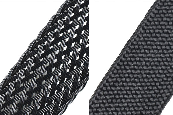
This is where braided sleeving makes a real difference:

  • Abrasion resistance – Prevents damage from edges and continuous movement.
  • Flame-retardant options – Essential for energy projects that must meet strict safety standards.
  • Easy installation – Expandable design works smoothly even on bulky or complex harnesses.
  • Durability in harsh conditions – Resistant to UV, chemicals, and long-term mechanical stress.

How MJ Delivers the Right Solution

At MJ, we support industries ranging from clean energy to industrial automation and aerospace with customized braided sleeving solutions. We don’t just supply a product — we help our customers select the right option for their exact needs:
  • Need abrasion resistance for moving cables? Choose our heavy-duty PET sleeving.
  • Need fire protection? Our flame-retardant grades are certified to international standards.
  • Need quick installation? Our self-closing and split sleeving makes assembly faster and easier.

On top of that, MJ provides:
  • High-volume production capacity to handle bulk orders quickly.
  • Consistent quality control at every stage of manufacturing.
  • Technical datasheets and certifications to support approval processes.

Proven Applications
  • Our braided sleeving is already used in:
  • Fuel cell systems – Safeguarding harnesses inside clean energy modules.
  • Industrial power and control wiring – Ensuring uptime and reliability.
  • Aerospace and defense – Lightweight and flame-retardant protection where it matters most.

The Bottom Line

If you are also looking for reliable cable harness protection for clean energy or industrial applications, MJ can provide the right braided sleeving — backed by expertise, certifications, and global delivery.

Current Transformer vs. Rogowski Coil Key Differences in Principle, Performance, and Applications

Current Transformer vs. Rogowski Coil: Key Differences in Principle, Performance, and Applications


In modern electrical and electronic measurement, the ability to capture stable and accurate current values is critical for power system monitoring and industrial equipment protection. Two widely used tools for current measurement are the Current Transformer (CT) (Figure 1) and the Rogowski Coil (Figure 2). While both serve the same fundamental purpose—measuring current—their working principles, performance characteristics, and application scenarios differ significantly. Choosing the right device for the right situation can greatly improve measurement accuracy and reliability.


Figure 1


Rogowski Coil


Figure 2


1. Working Principle


Current Transformer (CT)

A current transformer operates on the principle of electromagnetic induction. It typically consists of a magnetic core with a primary and secondary winding:

Primary winding: Few turns, thicker conductor, connected in series with the measured circuit.

Secondary winding: Many turns, thinner conductor, connected to measuring or protection devices.

When current flows through the primary, an alternating magnetic field is generated in the core. This induces a proportional current in the secondary winding according to the turns ratio. CT performance therefore depends heavily on the magnetic coupling and core material.

Rogowski Coil

A Rogowski coil, in contrast, uses an air-core coil instead of a magnetic core. By winding a helical coil around the conductor under test, it captures the rate of change of magnetic flux. The induced voltage in the coil is proportional to the rate of change of current. With appropriate signal integration, the actual current waveform can be reconstructed.

Because it has no core, the Rogowski coil is free from magnetic saturation, making it highly suitable for measuring very large and rapidly changing currents.


2. Performance Characteristics


Measurement Range

CTs are ideal for low to medium frequency and steady-state large current measurements, typically ranging from hundreds to thousands of amperes. However, they are limited by core saturation under overload conditions.

Rogowski coils have a wide frequency response and can measure currents from milliamperes to mega-amperes, including fast transient and pulsed currents.


Accuracy and Linearity

CTs provide high accuracy at power frequency (50/60 Hz), making them reliable for metering and protection. But when saturation occurs, nonlinear distortion may appear.

Rogowski coils offer excellent linearity over a wide dynamic range, with minimal error even under extreme current variations.


Frequency Response

CTs: Limited by magnetic core and typically designed for power frequency applications.

Rogowski coils: Capable of capturing high-frequency and transient events, making them indispensable for advanced testing environments.


3. Application Scenarios


Current Transformers (CTs)

Due to their maturity, precision, and robustness, CTs are widely used in:

Power systems: Measurement and protection in substations and transmission lines.

Industrial monitoring: Motors, transformers, and large electrical loads.

Energy metering: Utility-grade accuracy for billing and monitoring.


Rogowski Coils

Because of their wide bandwidth and non-intrusive nature, Rogowski coils are typically applied in:

High-frequency current measurement: Such as in switching power supplies.

Transient current detection: Capturing surges, spikes, or fault currents.

Power electronics and EV charging: Monitoring rapid current fluctuations in modern system.


4. Comparison Table: CT vs. Rogowski Coil


Feature Current Transformer (CT) Rogowski Coil
Core Design Magnetic core (prone to saturation) Air-core (no saturation)
Measurement Range Hundreds to thousands of amperes mA to MA (very wide dynamic range)
Frequency Response Low to medium frequency (50/60 Hz focus) Wideband, ideal for high-frequency
Accuracy at 50/60 Hz High accuracy, widely used in metering Good, but depends on signal processing
Applications Power systems, industrial monitoring Power electronics, transient analysis

Current Transformers (CTs) are the go-to choice for low-frequency, steady-state, high-accuracy current measurement, especially in power systems and energy metering.

Rogowski Coils excel in high-frequency, transient, and wide-range current monitoring, making them essential in power electronics, switching devices, and EV charging systems.


By understanding these distinctions, engineers and buyers can select the most suitable tool for their project needs, ensuring greater accuracy, reduced error rates, and improved system reliability


Relevant external links related to the key differences between Current Transformers (CT) and Rogowski coils:

Explanation of the working principle of Current Transformers, including detailed operation and safety considerations

A technical PDF explaining the Rogowski coil principle, how it measures rate of change of current, and the role of integration
Comparison highlighting advantages of Rogowski coils over conventional CTs, including installation flexibility and measurement range
Description of key applications of Current Transformers in power systems, metering, protection, and renewable energy
Overview of typical applications where Rogowski coils excel, such as precision welding and arc melting furnaces, showing their precision and non-intrusive nature
Wikipedia page summarizing Rogowski coil design, function, and typical usage scenarios, including their air-core construction and integration requirements


How to Prevent Cable Wear and Tear in Semiconductor & Medical Equipment

In industries like semiconductor manufacturing, medical devices, and aerospace, every detail matters. A single cable failure can lead to costly downtime, disrupted operations, and in some cases, serious safety risks. While cables and hoses may look minor compared to the equipment they power, their protection is critical for ensuring reliability and longevity.


The Problem: Cable Wear in High-Precision Environments

Cables in semiconductor fabs, medical laboratories, or aerospace systems are constantly exposed to:
  • Friction and vibration from moving machinery parts
  • Sharp edges inside enclosures and equipment frames
  • Cleaning agents and solvents used in maintenance
  • Frequent handling during installation or inspection

Over time, these stress factors cause abrasion, cuts, and premature failure of cables. In a cleanroom, even a small damaged cable jacket can release particles that compromise product quality. In medical devices, damaged wires may result in unexpected downtime or costly repairs.

Why Cable Protection Matters

A worn-out cable doesn’t just mean replacing one wire — it can:

  • Cause unplanned downtime in high-value production lines
  • Increase maintenance costs with frequent repairs
  • Jeopardize compliance with safety and cleanroom standards
  • Shorten equipment lifespan due to recurring failures

Preventing wear and tear at the source is far more cost-effective than dealing with failures later.

The Solution: Abrasion-Resistant Braided Sleeving

One proven way to protect cables is by using abrasion-resistant braided sleeving. Among the most effective solutions is PET high anti-abrasion expandable sleeving.

Key advantages include:

  • Superior abrasion resistance – up to 3x better than standard PET sleeves
  • Temperature stability – performs reliably from −40°C to +150°C
  • Chemical resistance – withstands oils, solvents, and cleaning agents
  • Lightweight and flexible – easy to install, even over long cable runs
  • Compliance – RoHS and halogen-free, suitable for sensitive environments

For example, MJ's BRS-PET-003-BK-HA (black, high anti-abrasion PET sleeve) and BRS-PET-020-WH (white, abrasion-resistant PET sleeve) are widely used in semiconductor tools and medical equipment. They help extend cable service life, improve system reliability, and ensure compliance with international standards.

Best Practice for Engineers

To maximize protection:
  • Choose the right size of sleeving for a snug but flexible fit.
  • Use color-coded sleeves to simplify maintenance.
  • Install sleeves in high-friction zones first, such as where cables contact moving machine parts.
  • Request abrasion test data from your supplier to verify performance in your specific application.

In precision industries, protecting cables is protecting productivity. By choosing abrasion-resistant braided sleeving, you can prevent premature cable wear, reduce downtime, and extend the lifespan of your critical equipment.

If you're looking for the best abrasion resistance at room temperature, we recommend testing MJ's High Anti-Abrasion PET Sleeving. Samples are available for evaluation.

Military-Grade Cable Protection Solutions

our one customer is a renowned provider of military-grade embedded computing systems, rugged displays, environmental testing equipment, and full turnkey solutions for defense, aerospace, telecommunications, and medical sectors.
Their high-demand applications require cable management components that offer exceptional durability, flame resistance, and ease of maintenance.


Xiamen MJ Industrial Tech Co., Ltd. provides a one-stop solution tailored for such demanding environments:


  • Flame-Retardant PET Expandable Braided Sleeving: Offers self-extinguishing properties according to UL94 V0, protecting cable bundles from heat and fire hazards in confined electronic systems.
  • Self-Wrapping Split Braided Sleeve: Enables quick installation and removal, ideal for systems requiring frequent servicing or modular upgrades.
  • Nylon Expandable Braided Sleeving: Delivers light-weight abrasion-resistant protection, adaptable to cables and hoses in constrained assemblies.
  • Hose Sleeving & Wire Loom: Ensures flexible yet rugged routing of hoses and wire bundles within embedded chassis or control consoles.
  • Insulation Sleeves (Heat-Shrink, Glass Fiber, Fire Sleeve): Offers targeted electrical insulation and thermal protection in high-voltage or high-temperature test modules.
  • Hook and Loop Fasteners: Provides fast cable bundling and tidy routing while maintaining tool-less access for field technicians.
  • Cable Glands (Nylon/Metal): Ensures environmental sealing and strain relief at cable entry points on rugged hardware enclosures.

Why MJ is the Right Partner


  • Quality & Certifications: ISO9001, ISO14001, IATF16949, and EN45545 systems are in place; products certified by UL, RoHS, REACH, and halogen-free standards
  • Proven Export Experience: Serving 87+ countries, with robust logistics and export capabilities
  • Strong Production Capacity: 14,000 m² manufacturing facility, backed by experienced engineers and quality control staff
  • Value-Added Services: Includes ODM development, free sampling, pre-cutting, custom packaging—perfect for customized Avdor needs.
  • Responsiveness: Dedicated account management ensures ordering and delivery are swift—even for urgent or small-batch deployments.

Tinned Copper vs. Silver Plated Copper Braided Sleeving Which One Is Right for Your Application?

When it comes to shielding and protecting cables in demanding environments, the choice of braided sleeving material can make a significant difference. Two popular options are Tinned Copper Braided Sleeving and Silver Plated Copper Braided Sleeving. Each offers unique benefits tailored to specific applications. Let's break down the key differences to help you make an informed decision.


Base Material
Tinned Copper: Pure copper wire with a tin plating.
Silver Plated Copper: Pure copper wire with a silver plating.

Main Function
Tinned Copper: Prevents copper oxidation and enhances corrosion resistance.
Silver Plated Copper: Offers superior conductivity, high-temperature resistance, and excellent oxidation resistance.

Conductivity
Tinned Copper: Good conductivity, though slightly lower than silver-plated options.
Silver Plated Copper: Excellent conductivity, second only to pure silver.

Temperature Resistance
Tinned Copper: Withstands temperatures up to 150–200°C.
Silver Plated Copper: Handles 200–250°C, with some grades enduring up to 300°C.

Flexibility & Solderability
Tinned Copper: Flexible with good solderability.
Silver Plated Copper: Even more flexible, ensuring reliable electrical contact.

Service Life
Tinned Copper: Moderate lifespan, ideal for standard applications.
Silver Plated Copper: Longer service life, perfect for long-term and mission-critical uses.

Cost
Tinned Copper: Cost-effective and affordable.
Silver Plated Copper: 3–5 times more expensive due to premium performance.

Typical Applications
Tinned Copper: Cable shielding, automotive, marine, telecommunications, and power equipment.
Silver Plated Copper: Aerospace, military, high-frequency signals, and medical instruments.


Tinned copper braided sleeving is a reliable, cost-effective solution for general industrial shielding needs. Silver plated copper braided sleeving delivers top-tier performance for high-frequency, high-temperature, and critical environments.

Whether you're working on everyday industrial projects or cutting-edge aerospace technology, choosing the right braided sleeving can enhance performance, durability, and reliability.

Upgrade your cable management with the right shield—choose wisely!