The Heart & Brain of a Humidifier How a Superior Control Circuit Board Elevates Your Product Competitiveness?

In dry seasons, humidifiers are our best allies for maintaining indoor comfort. But have you ever wondered what silently orchestrates this device, enabling it to intelligently adjust humidity, switch modes, and ensure safety?


In the highly competitive humidifier market, while industrial design may catch the consumer's eye, it is the "core" that determines user retention and brand reputation. Have you considered why one humidifier is praised as "smart, quiet, and safe," while another is flooded with negative reviews for "dry burning, noise, and control failure"?


The answer lies in the Humidifier Control Circuit Board (PCBA). It is not only the device's "brain," handling complex logic, but also its "heart," driving core components efficiently. For brand owners, a high-quality PCBA means lower after-sales rates and a higher brand premium. Today, we delve into this core component from a manufacturing and design perspective.

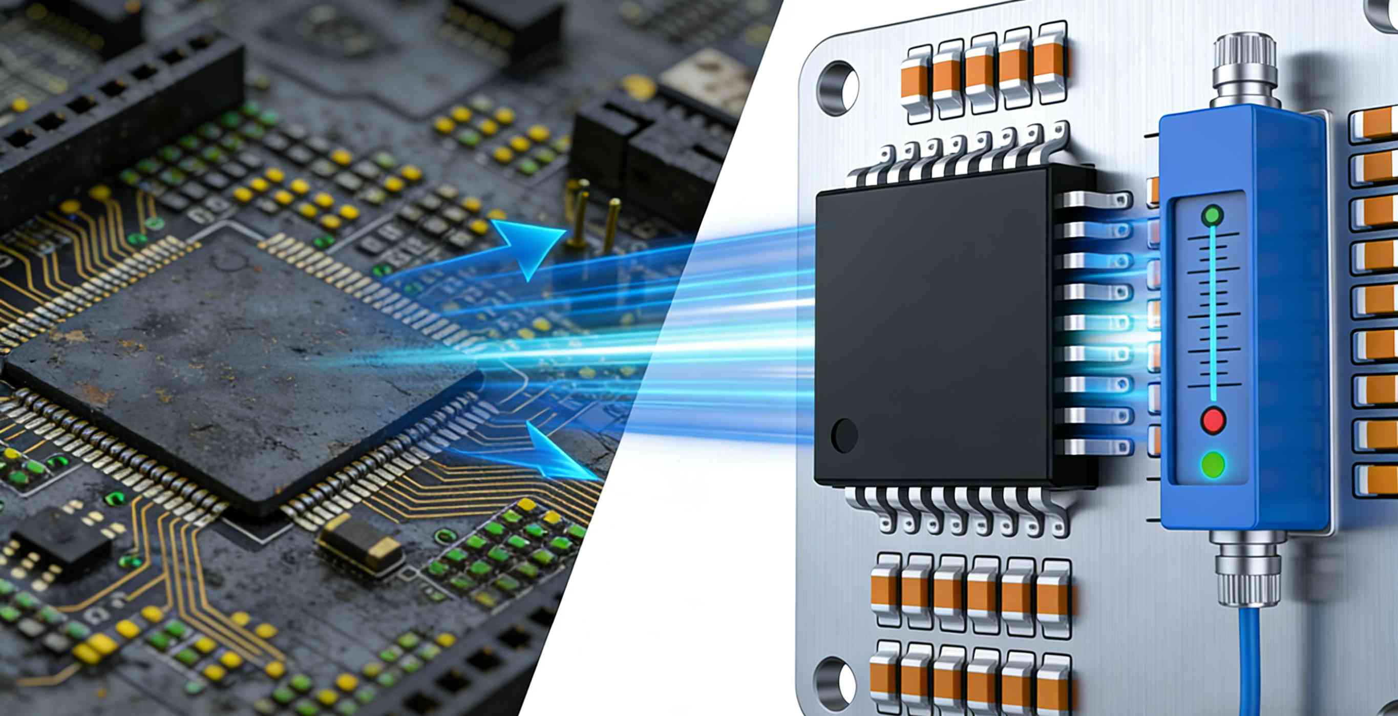
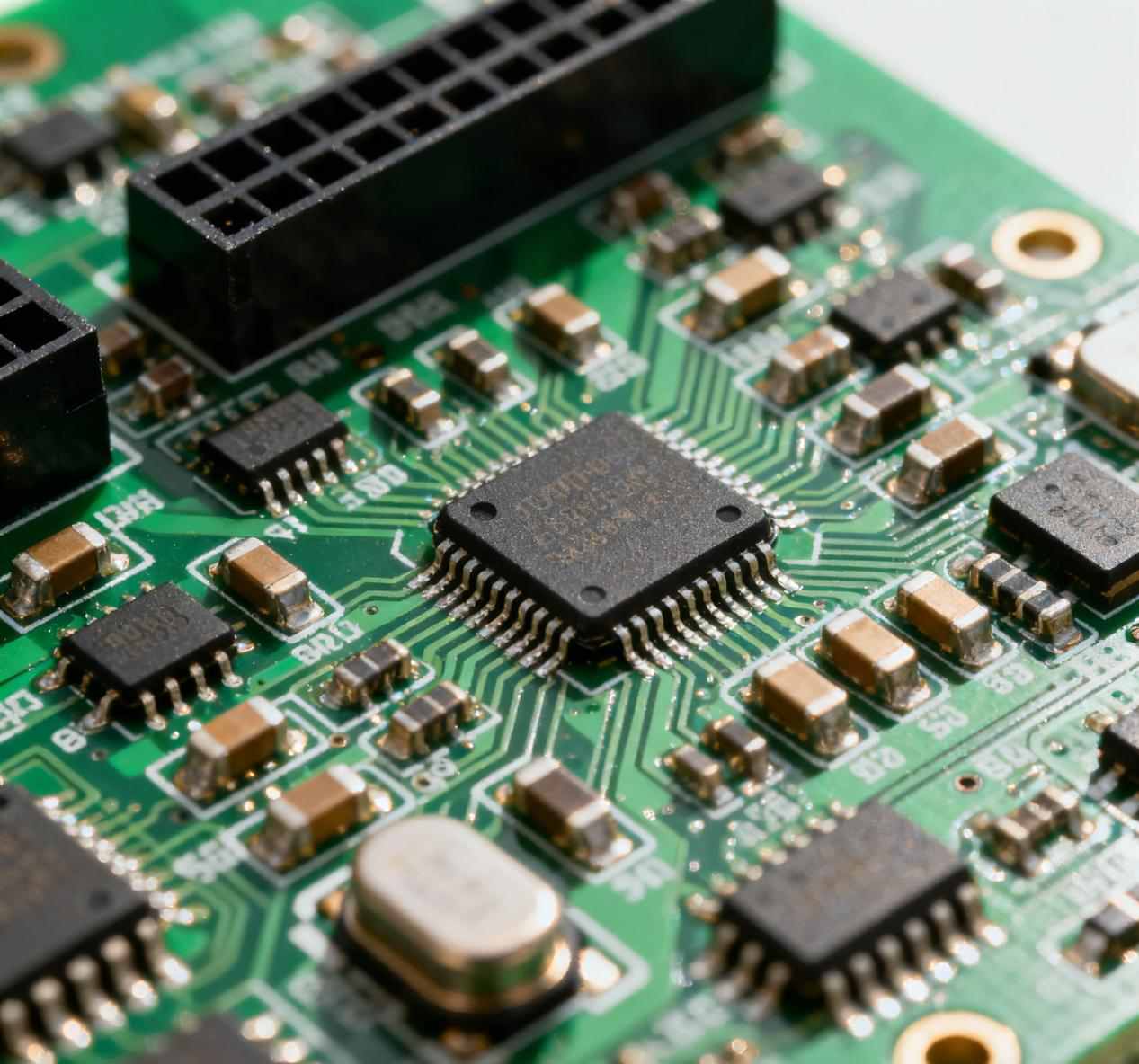
Silent energy-efficient ultrasonic humidifier home application


1.The Control Circuit Board: The Intelligent Command Center

Imagine the control circuit board as a micro-computer integrated onto a rigid plate. It receives "commands" from the user or the environment and then precisely drives the humidifier's various parts to execute tasks. Without it, a humidifier is merely a soulless shell.


2.Core Components: The Anatomy of a Superior PCBA

A High-Performance Humidifier Control Board typically consists of the following key sections:

1. MCU (Microcontroller Unit):

This is the true "brain." It is a chip integrating a processor, memory, and I/O ports, responsible for executing preset programs and handling all data and logical judgments.


2. Sensor Interfaces:

  • Humidity Sensor: Real-time monitoring of environmental humidity, feeding data back to the MCU. This is the cornerstone of automatic constant humidity functions.

  • Water Level Sensor: Detects the water tank level and automatically cuts power when water is low to prevent dry burning and ensure safety.

  • Temperature Sensor (Optional): Used in high-end models to provide more precise environmental data.


3. Power Control Unit:

  • Transistors/MOSFETs: Acting as electronic switches, they precisely control the power of the atomizer (ultrasonic type) or heater (evaporative type) based on MCU instructions to regulate mist volume.


4. User Interface (UI):

  • Buttons/Touch Interface: Receives user commands for power, humidity adjustment, timers, etc.

  • LED Display/Indicator Drivers: Clearly shows the user the current status, set humidity, and error codes.


5. Power Management Unit:

Converts household AC power into the stable DC power required by the circuit board and components, serving as the energy guarantee for the system's stable operation.

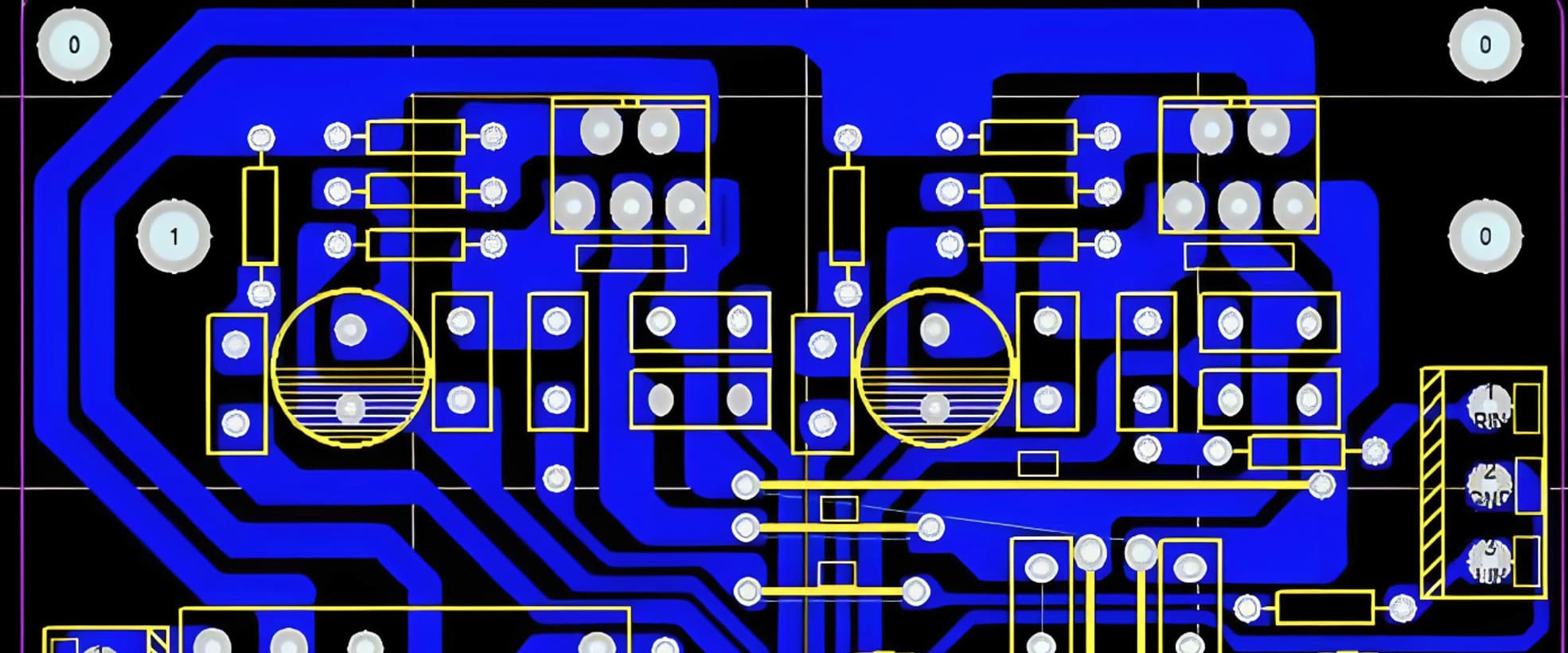
High-precision custom smart humidifier control circuit board


3.How Does Smart Control Work? A Closed-Loop Process

The intelligent control of modern humidifiers is a classic closed-loop automatic control system:

  1. Target Setting: You set the desired humidity (e.g., 50%) via the panel.

  2. Real-Time Monitoring: The humidity sensor continuously measures the room (e.g., currently 40%).

  3. Decision Making: The MCU compares the target with the actual value and detects low humidity.

  4. Command Execution: The MCU activates the atomizer at high power through the power control unit.

  5. Feedback Loop: As the humidifier works, the sensor detects the rising humidity.

  6. Equilibrium: When humidity reaches 50%, the MCU instructs the atomizer to lower power or enter standby mode to maintain equilibrium.

This cycle repeats continuously, achieving true "unattended" intelligent constant humidity.


4.Why is a Premium Circuit Board Crucial?

Choosing a humidifier equipped with a high-quality control board means you gain:

  • Precise Humidity Control: Avoids over-humidification or insufficiency, ensuring better comfort and protecting furniture and books from moisture damage.

  • Comprehensive Safety: Reliable protection against dry burning and electrical overload eliminates safety hazards.

  • Lasting Performance: Utilizing high-quality components and rational circuit design ensures long-term stability and reduces failure rates.

  • Rich Smart Features: Support for App control, voice assistant integration, timers, and multiple modes—all rely on powerful board design.

  • Energy Efficiency: Precise power control prevents energy waste.


5.Selecting the Right Control Circuit Board

When selecting or designing a humidifier, do not focus solely on tank capacity or exterior design. The internal control circuit board is the key to determining product competitiveness and user experience. Though small, it carries the heavy responsibility of intelligence, safety, and reliability.


Tailored for Your Business

Are you looking for reliable, high-performance humidifier control board solutions?

Ruichun is an expert in the design and manufacturing of smart home appliance control boards. We provide more than just circuit boards; we offer:

  • Customized Development: Tailored PCBA design solutions based on your product positioning and functional requirements.

  • Stability & Reliability: Using industry-leading components and strict production processes to ensure excellence in every board.

  • Cost Optimization: Leveraging our extensive experience to provide you with the most competitive BOM cost solutions.

  • Full-Cycle Technical Support: From concept to mass production, we offer end-to-end technical support to help you capture the market quickly.

Contact us today for a free technical consultation. Let us inject a powerful "Heart & Brain" into your next star humidifier product!

Unlocking Miniaturization Why High-Density Interconnect (HDI) PCBs Are Essential for Modern Electronics?

In today's pursuit of thinner, lighter, and more powerful devices, traditional PCB technology has reached its physical limits. When your design needs to accommodate a BGA chip with hundreds of pins, or integrate wireless communication, sensors, and processors into the space-constrained motherboard of a smartwatch, High-Density Interconnect (HDI) PCBs are no longer an "advanced option," but a necessity for achieving product innovation.


HDI technology achieves higher wiring density and electrical performance in a smaller space through a series of precision processes, making it the core engine of miniaturization for modern electronic devices.

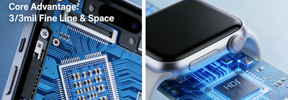
High Density Interconnect HDI PCB Structure Diagram

1. Why Has HDI PCB Become the Industry Benchmark?

HDI PCBs are not limited to high-end smartphones; they have penetrated all fields with stringent requirements for space, weight, and performance. Here is how they are applying to core sectors:

  • Smartphones and Portable Devices: Essential for packing powerful processors and batteries into slim profiles.
  • Wearable Devices: Smartwatches and AR/VR glasses rely on HDI to maintain lightweight designs without sacrificing functionality.
  • Automotive Electronics: Modern vehicles require sophisticated electronics. For example, an Automotive Grade 8-Channel Matrix LED Driver Board relies on HDI technology to manage complex thermal dissipation and high-current circuits within compact headlight assemblies.
  • High-Speed Communication: Routers, switches, and optical modules utilize HDI to ensure signal integrity at high data transfer rates.


2. Unveiling the Core Advantages: More Than Just "Smaller"

A. Space Magician: Higher Wiring Density

Technical Features: Supports extremely fine linewidths and pitches (typically 3/3 mil, advanced processes can reach 2/2 mil or even smaller), and widely utilizes microvias (diameter typically ≤0.15mm), blind vias, and buried vias.

Design Value: Allows for traces directly beneath the chip, perfectly supporting fine-pitch BGA, CSP, and QFN packages. This enables mounting components on both sides of the board, effectively doubling the component count.

B. Performance Booster: Superior Electrical Characteristics

Technical Features: Shorter electrical paths and fewer via fragments reduce signal loss.

Design Value: Reduced signal propagation delay and inductance/capacitance effects provide superior signal and power integrity. This is particularly crucial for consumer electronics like an Fan Motor Driver PCBA with Stepless Speed Control, where precise signal control and noise reduction are critical for user experience.

C. Reliability Guardian

Technical Features: Advanced stack-up structures and material selection (e.g., high-frequency/high-speed substrates).

Design Value: Better thermal management and mechanical stability, meeting the stringent reliability requirements of automotive electronics, aerospace, and medical fields (e.g., IPC-6012 Class 3 standard).


3. Key Considerations for Successful HDI Design

Early collaboration with HDI manufacturers is crucial for project success. Here are key points to communicate during the design phase:

  1. Define the Technology Level: How many layers of HDI does your design require? 1-layer (1+N+1), 2-layer (2+N+2), or any-layer? This directly determines cost and capability limits.
  2. Minimum Via/Pad Size: Clarify the limits for microvias to ensure manufacturability.
  3. Linewidth/Spacing Capability: Determine the minimum value (trace/space) that the manufacturer can reliably mass-produce.
  4. Layer Stack & Materials: Is it necessary to use low-loss (Low Dk/Df) materials to meet high-speed requirements?
  5. Design-for-Manufacturability (DFM): Reviewing the design with the manufacturer before production avoids costly rework.


4. Choosing a Professional HDI Manufacturer

When facing the complexities of HDI processes, choosing a partner with extensive experience is crucial. You need a manufacturer that offers comprehensive services.

Look for a provider capable of Custom PCB Fabrication. This ensures they have the mature process systems, advanced laser drilling equipment, and the ability to handle hybrid technologies required for complex projects.

Why do top global smart home appliance brands choose Ruichun as their core PCBA partner?

In the fiercely competitive smart home appliance PCBA market, a stable, efficient, and cost-optimized appliance control board is the cornerstone of product success. As a professional PCBA manufacturing service provider, we deeply understand that true value lies not only in price, but also in the perfect combination of technological leadership, ultimate reliability, scalable delivery capabilities, and deep customer collaboration.


Zero-Defect Quality Control for the Global Market

We employ top-tier hardware quality control standards throughout the entire PCBA design, manufacturing, and testing process. Leveraging 3D SPI, AOI, X-Ray, and customized FCT functional testing, we ensure flawless soldering and functionality in every high-reliability PCBA. Our 100% traceable component supply chain provides a solid guarantee for your products to obtain global certifications such as CE, UL, and FCC, making us a trustworthy one-stop PCBA solution provider.


Deep technical expertise in smart home appliances

We offer comprehensive PCBA technical services, from schematic design, PCB layout optimization, and embedded software development (supporting Wi-Fi/Bluetooth/Zigbee/IoT protocols) to sensor calibration and motor drive design. With extensive experience in smart home appliance control board design, we excel at significantly reducing your overall BOM cost while maintaining performance through Design for Manufacturability (DFM) and Design for Cost (DFC).


 Efficient supply chain and delivery designed for scalability

As a Professional PCBA manufacturer, we have established strategic partnerships with major chip manufacturers such as TI, ST, and Nordic to ensure the security of our component supply chain. Our SMT production line supports flexible switching from small-batch PCBA prototyping (delivery in as little as 24 hours) to mass production of millions of PCBAs, and provides transparent production progress management through a dedicated client portal.


We focus on serving the following types of clients:

• Smart home hardware brands: Providing complete PCBA solutions that meet target market certifications

• Amazon/Google ecosystem partners: Deeply understanding the specific requirements of the platform for smart hardware PCBAs

• Startup hardware companies: Providing full-process technical guidance from PCBA prototyping to mass production

• Traditional home appliance manufacturers: Providing high-reliability control boards for product intelligent upgrades


Clear and Efficient PCBA Collaboration Process

We have established a standardized PCBA production process: from requirements analysis, solution design, prototype production, functional verification to mass production and quality assurance, each step is equipped with a professional team to ensure the efficient progress of your smart home appliance PCBA project. We place particular emphasis on PCBA design-for-testability, providing customers with complete ICT testing and FCT testing solutions.


As a leading PCBA service provider, we are committed to helping customers shorten time-to-market, reduce production costs, and enhance market competitiveness through professional technology and strict quality control. We offer free PCBA design feasibility assessment services. We welcome you to submit your project requirements to obtain customized cost optimization solutions and technical support.


Choosing us means not just choosing a PCBA supplier, but also choosing a strategic partner who deeply understands the smart home appliance industry and can provide comprehensive technical support for your products.

Stop the "Fish-Mouth" Failure Why Your EV Harness Needs 175°C Stay-Closed Sleeving

The Hidden Risk in EV High-Voltage Systems


If you’re designing wire harnesses for EV battery packs or inverters, you’ve probably seen it: a standard self-wrapping sleeve that looks great on the assembly line, but after a few thermal cycles, it starts to warp, curl, and spring open.

In the industry, we call this "fish-mouthing." In a high-voltage environment, an open sleeve isn't just an aesthetic issue—it's a major safety risk.


Why 125°C Rated Sleeves are Failing


Standard PET wraps are typically rated for 125°C. However, in today's compact, high-energy-density battery packs, local "hot spots" can easily exceed these limits. This is where most protection fails.


That's why we engineered the E-FLEX® 175°C High-Temp Self-Wrapping Sleeving. We didn't just want a "tougher" sleeve; we wanted one that stays closed when the heat is on.


The E-FLEX® Advantage: What Makes it the "Stay-Closed" Champion?


175°C/240H Reality Check:

Most data sheets look good on paper, but we put E-FLEX® high temp sleeving through an intensive 175°C endurance test for 240 hours. The result? Zero opening, zero deformation. It retains its 360° protective seal even at peak thermal loads.


The "Hybrid Weave" Secret:

We use a strategic mix of stiff monofilament (for permanent spring-back memory) and soft multifilament (for full-surface coverage). It's flexible enough for tight bends but stubborn enough to keep its shape.


Slash Your TCO:

Because E-FLEX® high temperature wire cover stays closed on its own, you can ditch the secondary zip ties and messy adhesive tapes. It's a "snap-on" fix that reduces assembly time and survives the life of the vehicle.


Stop Settling for "Good Enough" Protection

In the world of electrification, "good enough" usually ends in a recall. If your current sleeving can't handle a 175°C/240H stay-closed test, it's time for an upgrade.

Does High-Density Cable Sleeving Prevent Liquid Damage?

Cables in industrial environments rarely exist in isolation—they are often integrated into complex machinery, production lines, or vehicle systems. Even when a cable appears robust on the outside, exposure to liquids and chemicals can silently degrade its performance over time.

This is where high-density cable sleeving plays a critical role. Unlike standard braided sleeving, high-density designs significantly reduce gaps in the braid structure, creating a stronger physical barrier against liquid intrusion.


Why Density Matters in Cable Sleeving

When selecting high-density cable sleeving, density is not a vague concept—it is defined by specific technical parameters that directly affect protection performance:


Parameter Description Impact on Corrosion & Liquid Resistance
Monofilament Diameter The thickness of each individual strand in the braid Thicker monofilaments provide stronger physical barriers and can withstand more aggressive spray and liquid exposure.
Carriers The number of spools on the braiding machine A higher carrier count (e.g. 24, 32, or 48 carriers) creates smaller, tighter mesh openings, significantly reducing liquid penetration.
Braid Angle The angle at which the strands intersect A more vertical braid angle improves longitudinal coverage, while a more angled braid can introduce gaps that allow liquid ingress.


When Standard Sleeving Is Not Enough

Even premium materials can fail if the braid density is insufficient. In environments such as food processing plants, chemical facilities, automotive engine compartments, or hydraulic systems, corrosive liquids often find their way through structural gaps.

To further enhance protection, engineers commonly adopt two proven solutions:

Overlap Design
Wrap-around or overlap sleeving introduces an intentional overlap zone along the edges, providing an additional barrier that blocks liquid entry points more effectively than traditional tubular designs.

Double-Layer Braided Sleeving
Applying two layers of high-density cable sleeving ensures that any gaps in the first layer are covered by the second. This method is widely used in aerospace and industrial applications for both chemical resistance and long-term durability.

Long-Term Reliability Through Smart Sleeving Selection
By focusing on braid density, structural parameters, and reinforcement methods, high-density cable sleeving delivers reliable protection against liquid exposure, chemical corrosion, and environmental wear. Proper selection during the design and specification stage ensures extended cable life and improved system reliability in demanding industrial conditions.

Future-Proof Cable Protection for European EV Charging Infrastructure

As Europe continues to expand its EV charging infrastructure, public charging stations are increasingly deployed in open, long-term operating environments. For project owners and integrators, reliability, operational continuity, and ease of maintenance are critical factors, while cable protection remains essential for ensuring long-term system performance.


Traditional EV charging cable sleeves focus mainly on abrasion resistance and basic environmental protection. While sufficient under standard conditions, European projects often require more robust solutions to meet the demands of public deployment, long-term operation, and compliance with EU standards. This shift has driven the adoption of anti-cut cable sleeves as part of comprehensive cable protection strategies.


By leveraging high-strength materials and optimized structural design, these sleeves disperse external forces, enhance system safety, and reduce the risk of cable damage, ultimately lowering maintenance needs and supporting reliable lifecycle performance. At the same time, they maintain the necessary flexibility and installation efficiency, ensuring smooth integration into existing EV charging networks.


Balancing enhanced protective performance with practical installation requirements, anti-cut cable protection is becoming a key solution for European renewable energy projects. It helps ensure safe, reliable, and long-lasting operation of EV charging infrastructure across public and open environments.

Hydraulic Hose Sheathing Pressure Rating vs. Oil Spray Protection Explained

In hydraulic systems, safety risks are often misunderstood. One of the most common misconceptions is treating hydraulic hose sheathing as a pressure-bearing component. In reality, hydraulic hose sheathing is designed primarily for oil spray containment and personnel protection, not for carrying internal system pressure.

hydraulic hose sheathing


Pressure Rating vs. Spray Containment

Pressure rating refers to the ability of a component to withstand internal fluid pressure without rupture. This applies to hydraulic hoses, valves, and fittings—not to external protective sheathing.

In applications such as pinch valves, hydraulic oil does not flow inside the sheathing. Under normal operation, the internal pressure inside the sheathing is effectively zero. The real risk arises when a hose, fitting, or valve fails and high-pressure oil is released at high velocity.

Hydraulic hose sheathing works by:

  • Blocking the direct spray path

  • Absorbing and dispersing jet energy

  • Converting dangerous oil jets into controlled seepage or dripping


How Hydraulic Hose Sheathing Reduces Risk


Sheathing Type Result
Low-density sleeve Oil jet passes through → injury risk
High-density nylon sheathing Jet hits fibers → dispersed → velocity reduced
Reinforced / dual-layer sheathing Enhanced containment → high-risk spray controlled


As long as the sheathing can disperse and redirect oil spray, it effectively protects personnel and surrounding equipment.


Choosing the Right Sheathing Based on System Pressure

The PN (Pressure Nominal) rating defines the safe operating pressure of valves and piping, not the sheathing. However, PN ratings help assess spray risk level, which guides protective sheathing selection.


System PN Rating Spray Risk Recommended Sheathing
PN6 Low Basic or optional
PN10 Medium High-density nylon sheathing
PN16 Medium–High Reinforced or dual-layer
PN25+ High Multi-layer or rigid protection


Hydraulic hose sheathing is a secondary safety barrier—essential for industrial risk control.


Why Buyers Look for New Suppliers Even When Products Are Already in Use

In many industrial applications, buyers reach out to new suppliers with a similar background:
the braided sleeving or cable protection products are already in use, and performance is generally stable — yet supplier evaluation is still ongoing.


braided sleeving


This does not necessarily mean that the existing supply chain has failed.
Instead, it reflects a growing focus on supply chain stability and controllability.


Supplier selection has become a standard procurement practice

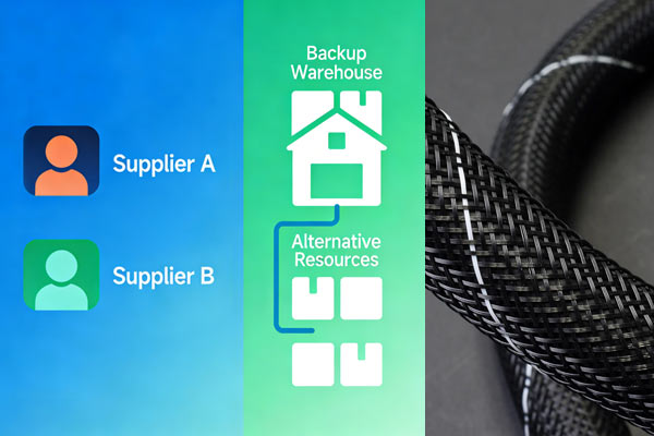
With fluctuations in raw material costs and increasing uncertainty in lead times, many procurement teams recognize that relying on a single supplier introduces hidden risks.

Even when current products meet application requirements, buyers often reassess their braided sleeving supplier selection if they encounter:

  • Limited pricing transparency

  • Unstable delivery schedules

  • Insufficient flexibility for customization

  • Lack of qualified alternative sources


A new supplier is often a complement, not a replacement

In most cases, buyers are not looking to immediately replace their existing supplier.
They are searching for an alternative that offers:

  • Comparable technical specifications

  • Competitive and transparent pricing

  • Stable production and delivery capacity

  • Long-term cooperation potential

That is why early discussions usually focus on technical equivalency and specification matching, rather than price alone.

For suppliers, the real value lies in providing clear technical documentation, reliable quality, and predictable supply, which are essential factors in professional braided sleeving supplier selection.

Why PEEK-Aramid Hybrid Sleeving is the New Standard for eVTOL and Aerospace Cable Protection

As electric aircraft, eVTOL platforms, and modern spacecraft continue to evolve, cable protection systems are facing a paradigm shift. Designers must now balance extreme weight reduction, thermal stability , and mechanical durability within increasingly compact systems.


While traditional metal braids have long been the EMI standard, the rise of lightweight aviation has pushed these materials to their limits. Emerging as the superior structural alternative is the STW-PEEK Series—a hybrid self-wrapping sleeve engineered with PEEK monofilaments (0.1–0.5mm) and high-tenacity Aramid multifilaments (200–8000 D).


Engineering for Extremes: Performance by the Numbers

To meet the rigorous demands of aerospace and military standards, the STW-PEEK Series is tested against the industry's most unforgiving protocols:

  • Thermal Endurance: Maintains full structural integrity from -60 to +260. Even after high-temperature aging, the tensile strength of the fiber filaments remains 0.01N/dTex.
  • Mechanical Resilience: Designed to withstand over 1000 bending cycles (under 10N load) and more than 100 scraping cycles against stainless steel needles without deformation or rupture.
  • Unrivaled Fluid Resistance: Engineered for engine nacelles, it shows zero damage when exposed to Skydrol (hydraulic fluid), JP-8 jet fuel, lubrication oils (8#, 12#), and aircraft de-icing fluids at 70±3.
  • Solar Radiation Resistance: Maintains over 45% tensile strength retention after 40 hours of continuous high-intensity solar radiation (1127±47W/).


The STW-PEEK Advantage: Weight vs. Protection


Property Traditional Metal Braid STW-PEEK Hybrid Sleeving
Material Copper / Aluminum PEEK + Kevlar (Aramid)
Wall Thickness Variable 0.78±0.10mm
Self-Weight High 15–204g/m(Model dependent)
Overlap Design None (Closed) 65°–130° Shape Memory
Anti-Fungal Moderate Grade 1 (Zero growth per GJB150.10A)


Safety & Survivability: Low Smoke, Zero Toxicity

1. Unmatched Weight Efficiency


PEEK (Polyetheretherketone) composites are significantly lighter than traditional metals. Utilizing STW-PEEK can result in a weight reduction of up to 40% compared to aluminum shielding components. In the aerospace sector, this translates to improved "Energy-to-Distance" ratios.

2. "Shape Memory" Self-Wrapping Architecture


Unlike traditional "sock-style" sleeves, the STW-PEEK features a side-entry, self-closing design with a permanent shape memory (offering 65° to 130° overlap).

  • Rapid Retrofitting: It can be installed over existing wire harnesses without disconnecting terminals.
  • Ease of Maintenance: Allows for quick inspection of cables, reducing aircraft AOG (Aircraft On Ground) time.

3. Extreme Thermal & Chemical Immunity

With a continuous service temperature of +260 , PEEK-Aramid blends remain stable where others fail. Furthermore, it is chemically inert to Skydrol (hydraulic fluid), JP-8 jet fuel, and de-icing agents, meeting the strict requirements of engine nacelle environments.


4. Superior Fatigue and Vibration Resistance

Metal braids are prone to "work hardening" and eventual cracking under the high-frequency vibrations of eVTOL rotors. The hybrid weave of STW-PEEK acts as a mechanical dampener, tolerating millions of vibration cycles while maintaining 100% coverage of the internal wire harness.


Specialized Benefits for Space Applications

In low-earth orbit (LEO) and deep space environments, the STW-PEEK offers unique advantages:

Fungal Resistance: Compliant with GJB150.10A-2009, ensuring zero biological growth in enclosed, humid spacecraft modules.

Low Outgassing: Essential for maintaining the vacuum integrity of satellite electronics.

Radiation Interaction: Unlike heavy metals, hydrogen-rich polymers like PEEK generate lower secondary radiation when struck by space particles.


The Future of Lightweight Aerospace Shielding

As the industry shifts toward "More Electric Aircraft" (MEA), the reliance on heavy, rigid conduits is fading. Advanced polymer composite sleeving like the STW-PEEK Series provides the missing link between extreme protection and lightweight design.

Whether you are designing a high-altitude UAV, a commercial eVTOL, or a satellite bus, the STW-PEEK offers the durability of metal with the agility of advanced polymers.


Module-Level Flame Retardancy Why UL94V0 Wrap Around Sleeves Require Structural Design

In industrial wiring harnesses and module-level applications, flame retardancy is not determined by material alone. For UL94V0 wrap around sleeves, true fire safety depends on whether the structure can self-extinguish quickly under heat and prevent flame propagation.

UL94 V0 raw material certification only proves that the material itself can self-extinguish—it does not guarantee safety once it is formed into a real wrap around sleeve structure.


Why UL94V0 Wrap Around Sleeves Need More Than Material Certification

Module-level flame retardancy is not about “non-flammable materials,” but about ensuring that the UL94V0 wrap around sleeve structure does not assist flame propagation.

At the module level, flame-retardant performance depends on structural factors such as:
  • Textile density
  • Wrapping coverage
  • Overlap design
  • Thermal stability

These critical factors are not reflected in UL94 raw material testing, which does not evaluate flame behavior after the sleeve is formed.


Does Higher Textile Density Always Improve Flame Retardancy?

The answer is no.

Higher textile density increases heat accumulation, reduces heat dissipation, and accelerates temperature rise, leading to continuous thermal decomposition of internal fibers.

In UL94 testing, the core requirement for V0 classification is rapid self-extinguishing after flame removal—not slower burning.

Some high-density UL94V0 wrap around sleeves show no open flame but continue glowing, smoking, and carbonizing—indicating structural failure rather than compliance.

Better structural design features:

Optimized textile density

Controlled oxygen pathways

Rapid interruption of combustion under heat exposure

Why Fully Enclosed UL94V0 Wrap Around Sleeves Can Be Dangerous

The real risk often comes from excessive coverage.
When coverage is too high, a semi-enclosed combustion environment forms inside the sleeve:
  • Higher internal temperature
  • Limited heat dissipation
  • Greater difficulty self-extinguishing once ignition occurs
Full enclosure does not mean non-flammability.

This explains why heat-shrink tubing often carbonizes at the ends, allowing flames to propagate inward along the tube.


Effective UL94V0 wrap around sleeve design should include:
  • Controlled overlap ratios
  • Defined heat-release paths
  • No continuous combustion channels
Overlap Design: The Most Overlooked Flame-Retardant Factor
Overlap design heavily impacts flame retardancy in self-wrapping sleeves.
Overlap too loose,Flames propagate through gaps;Overlap too tight , Heat accumulation prevents self-extinguishing.

Structures that truly pass finished-product UL94V0 wrap around sleeve testing must:
  • Maintain overlap integrity under heat
  • Avoid forming “combustion bridges”
  • Locally interrupt flame propagation
At this stage, the challenge is structural engineering, not material selection.

Thermal Stability: Why It Determines Real Safety
Thermal stability refers to whether a sleeve can maintain its original form and function after:
  • Flame contact
  • Flame removal
  • Secondary or repeated heat exposure
Many UL94V0 wrap around sleeves can self-extinguish initially, but their structure may already be deformed, shrunk, or collapsed—leading to immediate failure during subsequent heating.

UL94 raw material testing does not evaluate post-deformation behavior or repeated thermal exposure scenarios.

Core Criterion for Module-Level Flame Retardancy
The essence of module-level flame retardancy is that the structure must never assist flame propagation at any stage of heat exposure.

UL94 V0 material certification only proves self-extinguishing behavior of the material itself; real engineering safety depends on structural performance of UL94V0 wrap around sleeves in real applications.

UL94V0 Wrap Around Sleeves Common Questions
Q1: What does UL94 V0 actually test?
UL94 V0 tests the self-extinguishing behavior of raw materials under controlled conditions, not finished UL94V0 wrap around sleeves or assembled structures.

Q2: Why can materials pass UL94 but finished sleeves fail?
Because flame propagation, heat accumulation, and overlap behavior only appear after the sleeve structure is formed.

Q3: What causes flame propagation in UL94V0 wrap around sleeves?
Excessive coverage, improper overlap design, heat trapping, and insufficient thermal stability are the main causes.