MC3 and MC4 connectors are widely used in the solar energy industry for connecting photovoltaic (PV) panels to the rest of the solar power system. While both serve a similar purpose, they have distinct differences in design, functionality, and compatibility. Understanding these differences is essential for selecting the right connector for your solar installation.
| MC3 connectors |
MC3 connectors are a type of electrical connector commonly used in solar PV systems to connect solar panels together. The “MC” stands for “Multi-Contact,” a Swiss company that developed this type of connector. The “3” in MC3 refers to the 3 mm diameter pin used in these connectors. MC3 connectors are designed to provide a reliable connection between solar panels, ensuring that the electrical current flows efficiently from one panel to the next.
Design: Slim and lightweight, with a 3 mm contact pin.
Locking Mechanism: Snap-in design, less resistant to accidental disconnection.
Weather Resistance: Limited protection against environmental factors such as water and dust.
Usage: Commonly found in older solar panel systems or small-scale installations.
MC3 connectors
| MC4 connectors |
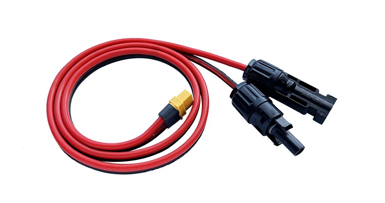
MC4 connectors, introduced as an upgrade to MC3, are now the industry standard for solar panel connections. They feature a 4 mm diameter pin, offering a more robust and secure connection. MC4 Solar Panel Adapter Cable has a locking system with a press-and-release mechanism, ensuring better safety and resistance to accidental disconnection.
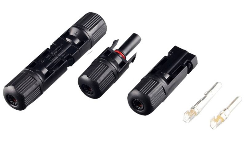
Design: Slightly larger than MC3, with a 4 mm contact pin.
Locking Mechanism: Secure press-and-release lock to prevent unintentional separation.
Weather Resistance: Fully sealed design, offering IP67-rated protection against water and dust.
Usage: The standard choice for modern solar systems, including large-scale and residential installations.
Differences Between MC3 and MC4 Connectors
Pin Diameter: The most obvious difference between MC3 and MC4 connectors is the pin diameter. MC3 connectors have a 3 mm diameter pin, while MC4 Adapter Plug Cable has a 4 mm diameter pin. This difference affects the amount of current each connector can handle.
Locking Mechanism: MC4 connectors feature a more advanced locking mechanism compared to MC3 connectors. The locking system in MC4 connectors ensures a more secure and stable connection, reducing the risk of accidental disconnection.
Current Capacity: Due to their larger pin size, MC4 connectors can handle higher current loads than MC3 connectors. This makes MC4 connectors more suitable for large-scale solar installations where higher currents are common.
Standardization: Solar Panel MC4 Connection Cable has become the industry standard for solar PV systems, while MC3 connectors are now less commonly used. This standardization means that MC4 connectors are more widely available and compatible with newer solar panels and equipment.
MC3 and MC4 connectors are both vital components in solar PV systems, providing the necessary connections between panels. While they share some similarities in function and design, the differences in pin size, current capacity, and locking mechanisms make them suitable for different applications. MC4 connectors, with their enhanced features, have become the industry standard, particularly in larger and more modern solar installations. Understanding these differences and choosing the appropriate connector type is crucial for ensuring the efficiency, safety, and longevity of your solar energy system.