Wire harnesses and cable harnesses are important in electrical systems. They have different uses. A wire harness groups single wires into an organized setup. This makes connections easier and less messy. A cable harness, on the other hand, wraps many wires or cables in a cover. This cover makes it stronger and protects it from damage.
The main differences are in their design and use. Wire harnesses work well in small, low-stress places, like car interiors. Cable harnesses are better for tough conditions, like outside, where they face water, heat, and wear. Both are important in industries like telecommunications. Custom Wiring Harnesses are made to fit specific needs.
Learn more about Custom Wiring Harness.
Key Takeaways
-
Wire harnesses keep single wires tidy, making connections simple and neat.
-
Cable harnesses group many wires in a tough cover, perfect for outdoor use.
-
Picking the right harness is important; wire harnesses work best indoors, while cable harnesses are great for outdoor jobs.
-
Custom harnesses improve performance by matching project needs, keeping things safe and reliable.
-
Good parts, like copper tube ends, help make strong and secure connections.
Key Features of Wire Harnesses
Structure and Components
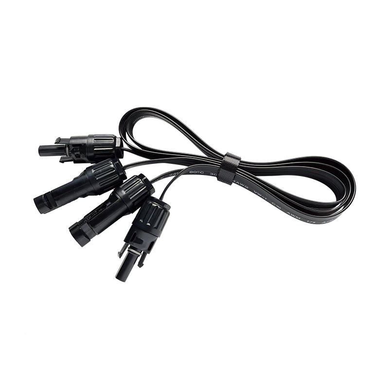
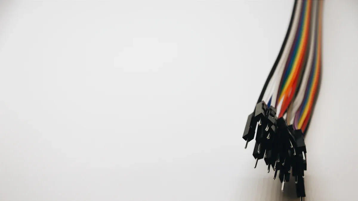
A wire harness groups wires into one neat bundle. Each wire has a job, like carrying power or signals. Materials like plastic ties or sleeves hold the wires together. This setup keeps wires tidy and stops them from tangling. Connectors, terminals, and covers are often included. These parts keep connections secure and protect wires from damage.
Wire harnesses are simple and easy to use. They don’t have thick insulation, so they are light and quick to install. This basic design lets you adjust the harness for specific needs. It can be made to fit exactly what you require.
Typical Applications
Wire harnesses are used in many fields. In cars, they link parts like lights, batteries, and sensors. In homes, they connect circuits in appliances to make them work. In factories, they organize complex wiring, making repairs easier.
They are great for places with little stress. For example, they work well indoors where wires are safe from tough conditions. This flexibility means wire harnesses can be used in many ways without losing efficiency.
Benefits of Using Wire Harnesses
Wire harnesses have many benefits, making them popular in industries. One big advantage is saving money. A study with a European car company showed that using similar harness designs reduces the number needed. This cuts costs and makes managing parts easier.
Another benefit is better organization. Bundling wires removes mess and lowers the chance of electrical problems. This neat setup also makes installation and repairs faster, saving time and effort.
Wire harnesses also improve safety. Their protective materials guard wires from harm, lowering the risk of short circuits or fires. This makes sure your electrical systems stay safe and work well.
Key Features of Cable Harnesses
Strong Protection and Long-Lasting Design
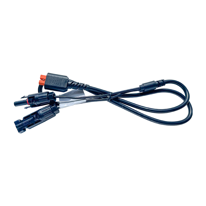
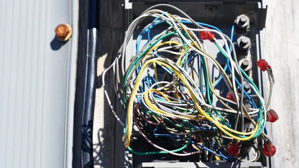
Cable harnesses are made to handle tough conditions. They protect wires by wrapping them in a strong outer cover. This cover keeps the wires safe from damage, water, and extreme heat or cold. Cable harnesses are great for places where wires face wear and tear often.
New testing tools have made cable harnesses even more reliable. These tools measure things like wire resistance and capacitance with high accuracy. A special four-wire test checks resistance as low as 1mΩ. This makes cable harnesses perfect for high-tech uses. Plus, these tools can be updated for future needs, keeping them useful as technology changes.
Where They Are Used
Cable harnesses are important in industries needing strong wiring systems. In cars, they connect parts like advanced driver-assistance systems (ADAS) and electric vehicle (EV) components. Passenger vehicles are the biggest users of cable harnesses.
Trucks and buses also use cable harnesses a lot. As these vehicles get more electronic systems, the need for strong harnesses grows. Lightweight materials are often added to save fuel, matching industry goals.
Why Choose Cable Harnesses Over Wire Harnesses
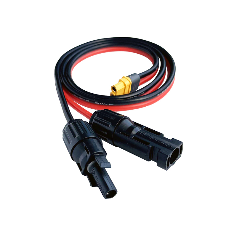
Cable harnesses have clear benefits over wire harnesses in tough settings. Their outer cover makes them stronger and better for outdoor use. They can handle water, heat, and wear without breaking.
Bundling many cables into one protected unit makes setup easier. Cable harnesses also lower the chance of electrical problems by shielding wires. They work well with new tech, like ADAS and EV systems, showing their value in modern designs.
Environmental Suitability
Indoor vs. Outdoor Applications
Think about where the harness will be used. Wire harnesses are best indoors. They work well in places without tough conditions. For example, they are used in home gadgets or office machines.
Cable harnesses are better for outdoor use. Their strong covers protect wires from bad weather. Rain, snow, or heat won’t stop them from working. This makes them great for outdoor machines, cars, and telecom tools.
Resistance to Environmental Factors
Cable harnesses handle tough environments better. They have layers that block water, dust, and heat changes. This keeps them working well for a long time.
Wire harnesses don’t protect as much. They can get damaged by water or sunlight. Use them indoors where these risks are low.
Choosing the Right Harness for Specific Conditions
Pick the right harness for your project’s needs. Wire harnesses are cheap and light, perfect for indoor jobs. They make wiring simple without heavy covers.
For outdoor or hard conditions, cable harnesses are best. Their strong build keeps wires safe and working well. Always check your project’s needs to choose wisely.
Industries and Applications
Automotive and Aerospace
Cars and airplanes need harnesses for their electrical systems. In cars, cable assemblies link parts like sensors, batteries, and ADAS. The rise of electric cars (EVs) has made wire harnesses even more important.
Airplanes need strong connections to handle tough conditions. These include temperature changes and vibrations. Cable assemblies keep airplane systems safe and working well. Below is a table showing how these industries use harnesses:
|
Industry |
Adoption Rate |
Key Drivers |
|---|---|---|
|
Automotive |
Over 80% |
More complex vehicle electronics and the shift to EVs. |
|
Aerospace |
Increasing |
Strict rules and the need for strong connections in harsh conditions. |
Both industries use custom cable assemblies for their needs. These improve performance and meet industry rules.
Telecommunications and Networking
Telecom and networking systems need cable assemblies for smooth data flow. These systems require strong and accurate connections for fast data transfer. Cable assemblies organize wires and protect them for steady communication.
In networking, custom cable assemblies link servers, routers, and other tools. They reduce mess and boost system performance. For outdoor setups, they guard against water and heat.
As telecom grows worldwide, the need for wire harnesses rises. Whether indoors or outdoors, cable assemblies help keep systems connected.
Role of Network Extension Cables in Harness Systems
Network extension cables are key in modern harness setups. They let networks reach farther, linking devices over long distances. These cables are used in homes, offices, and factories.
In harness systems, these cables add flexibility and scalability. They work well with custom cable assemblies and fit many devices. For example, they connect computers, printers, and medical tools to central systems.
When choosing network extension cables, think about length and durability. Good cables make systems reliable and prevent signal loss. Learn more about network extension cables here.
For custom solutions, work with a trusted copper tube terminal maker. This ensures your harness systems meet specific needs. Learn more about copper tube terminals here.
Custom Wiring Harness Solutions
Benefits of Customization
Custom wiring harnesses are made to fit your project needs. Each wire, connector, and terminal is designed to match perfectly. This setup makes systems work better and avoids electrical problems. For example, in cars, custom harnesses handle heat and vibrations well. This ensures they work reliably.
Custom harnesses also boost system performance. They keep signals clear and reduce interference. Custom designs follow industry rules, ensuring safety and reliability. Whether for small gadgets or big machines, custom harnesses adapt to your needs.
Importance of Copper Tube Terminal Manufacturers
Good wiring harnesses need quality parts, especially terminals. Copper tube terminals are key for strong and safe connections. A trusted terminal maker provides durable and high-performing parts.
Choose a manufacturer that focuses on quality and precision. Skilled workers and advanced tools make sure terminals meet standards. This is vital in fields like aerospace, where lightweight and heat-resistant parts are needed. Working with a reliable maker ensures your harness works well in tough conditions. Learn more about copper tube terminal makers here.
Factors to Consider When Designing a Custom Harness
Planning is important when designing a custom harness. First, think about what your project needs. For example, car harnesses must handle heat, while airplane harnesses need to be light. Knowing these needs helps you pick the right materials.
Next, design for better performance and safety. Use advanced tools to create a harness that avoids electrical issues. High-quality production ensures the harness meets safety rules.
Lastly, think about where the harness will be used. For outdoor use, pick materials that resist water, dust, and extreme weather. By considering these factors, you can make a harness that lasts and works well. Learn more about custom wiring harness solutions here.
For larger networks, add a Network Extension Cable. These cables make systems more flexible and easier to expand.
Wire harnesses and cable harnesses have different jobs. Wire harnesses keep wires neat and simple for safe spaces. Cable harnesses protect wires better in tough environments. Picking the right harness helps your project stay safe and last longer.
Choosing the right harness affects how well things work. For example, special harnesses in building sites cut accidents by 30%. In factories, better designs reduced worker discomfort by 40%.
|
Use Case |
Result Description |
Impact Percentage |
|---|---|---|
|
Construction |
Using special fall safety harnesses lowered workplace accidents. |
30% reduction |
|
Automotive |
Special harnesses with tools reduced tool-related injuries. |
25% reduction |
|
Manufacturing |
Comfortable harness designs reduced worker discomfort reports. |
40% reduction |
Custom wiring harnesses are made to fit your needs. Working with experts and trusted copper terminal makers ensures good parts. Always focus on quality and custom designs for the best results.