1、 Temperature control accuracy and stability advantages
- Closed loop control achieves constant temperature effect
The thermostat automatically starts and stops the heating cable by collecting temperature signals in real-time (such as PT100 sensor accuracy of ± 0.1 ℃), comparing them with the set value, to avoid significant fluctuations in "overheating cooling" of traditional heating methods (such as electric blankets).
Case: In a underfloor heating system, a temperature controller paired with carbon fiber heating cables can control the room temperature within a set range of ± 0.5 ℃ (traditional boiler heating temperature difference is usually ± 2 ℃).
- Flexible adaptation to different scene requirements
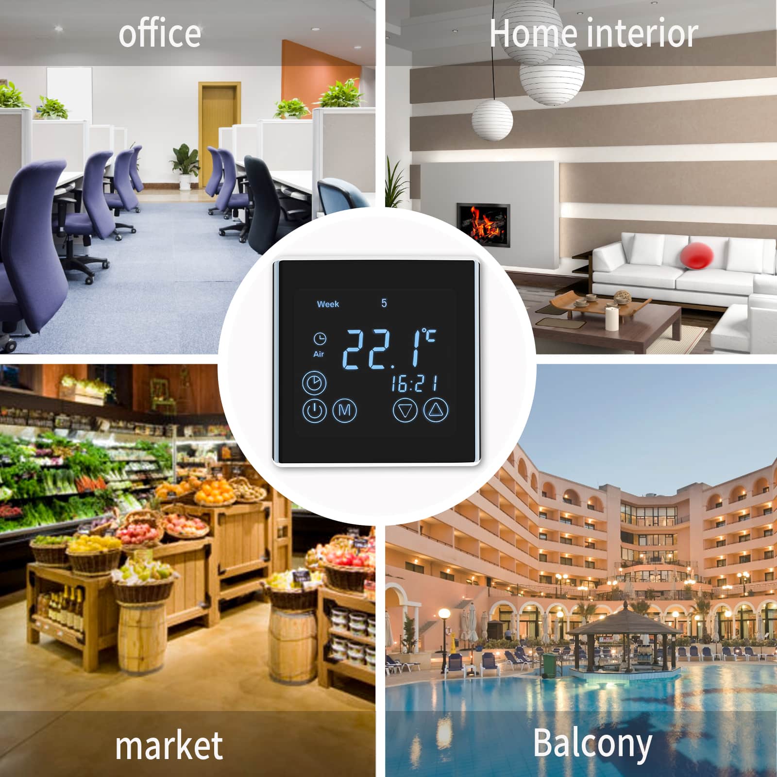
Programmable temperature controllers support temperature control in different time periods (such as 22 ℃ during the day and 18 ℃ at night), and with constant power heating cables, can customize temperature curves for greenhouse seedling cultivation, industrial pipelines, and other scenarios. Self limiting cables and mechanical temperature controllers are suitable for simple antifreeze scenarios (such as bathroom pipeline insulation).
2、 Energy utilization efficiency and energy-saving advantages
- On demand heating reduces ineffective energy consumption
The thermostat only activates the heating cable when the temperature is below the set value, avoiding heat waste caused by continuous heating. For example, in civil heating scenarios, compared to electric heaters that are constantly on for 24 hours, the temperature controller+heating cable system saves about 30% to 40% energy (data source: GB/T 39848-2021 Energy Efficiency Standard for Electric Heating Systems).
- Power matching optimization operating cost
The temperature controller is configured with a single load of 80% of the total power of the heating cable (leaving a 20% margin) to avoid power loss caused by the "big horse pulling small car". Taking 100 ㎡ underfloor heating as an example, a 2000W heating cable paired with a 2500W thermostat can reduce standby power consumption by approximately 120kWh per year compared to a 3000W thermostat.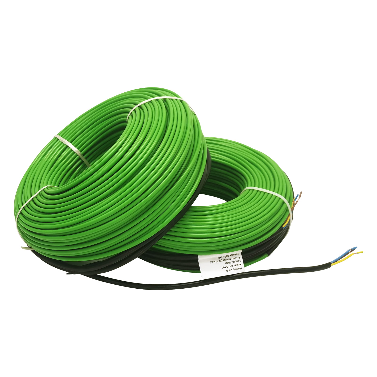
3、 Advantages of system security and reliability
- Multiple protections to prevent overheating risks
The temperature controller is equipped with built-in overheat protection (such as setting an upper limit of 60 ℃ for forced shutdown), combined with the insulation layer of the heating cable (such as PE sheath with a temperature resistance of 90 ℃), which can prevent local overheating from causing fires. In industrial scenarios, explosion-proof temperature controllers and MI mineral insulated heating cables can better meet the requirements of hazardous environments (such as gas station pipeline heating).
- Convenience of fault diagnosis and maintenance
The digital temperature controller can display temperature abnormal codes in real time, and with the segmented detection of heating cables, it can quickly locate the fault point, improving maintenance efficiency by more than 50% compared to traditional heating systems.
4、 Advantages of application flexibility and adaptability
- Multi scenario customized solution
- In the civilian field, temperature controllers and heating cables are installed in separate rooms to achieve differentiated heating of 22 ℃ in the master bedroom and 20 ℃ in the secondary bedroom;
- In the industrial field, in the heat tracing of storage tanks, the temperature controller can be linked with a liquid level sensor (to strengthen heating when the liquid level is low) to avoid medium solidification;
- In the agricultural field, heating cables are laid under the seedling beds, and the temperature controller automatically switches between "28 ℃ during the day/18 ℃ at night" to promote crop growth.
Compatible upgrade with intelligent systems
IoT temperature controllers (such as those with Modbus interfaces) can be connected to building control systems (BMS) and form an intelligent heating network with heating cables for "remote monitoring+big data analysis", suitable for large parks or data centers.
5、 Advantages in lifespan and maintenance costs
- Extend the service life of equipment
The "gap start" mode (non continuous operation) of the thermostat reduces the loss of heating cables during long-term full load operation. Carbon fiber heating cables can have a service life of 15-20 years under the control of the thermostat
- Reduce maintenance costs
The standardized interface between the thermostat and the heating cable facilitates the replacement of accessories, and the scale cleaning requirements of the waterless circulation system (compared to the water heating system) can reduce maintenance costs by more than 60% annually.
6、 Environmental and installation advantages
- Green, environmentally friendly, and pollution-free
The electric heating method has zero carbon emissions, and with the precise temperature control of the thermostat, it reduces about 2.3kgCO ₂/㎡ · year compared to gas boiler heating (taking Beijing as an example), which is in line with the trend of carbon neutrality.
- Easy installation and space saving
The heating cable can be laid in narrow spaces such as under the floor and on the surface of pipelines. The wall mounted installation of the temperature controller only occupies 0.02 square meters, saving 30% of installation space compared to traditional boiler+radiator systems.
The essence of the combination of the two is the deep integration of "intelligent control" and "efficient heating", which not only meets the basic heating needs, but also achieves multiple improvements in energy efficiency, safety, and experience through technological collaboration. It is the core technical solution of modern electric heating systems.